
带通滤波器计算器
这计算了Butterworth LC带通滤波器中使用的电感,电感和电容器的电感的值。
输出
计算带通滤波器的电感和电容
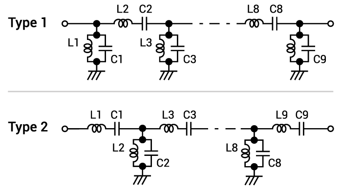
该计算器有助于确定电感器(L)和电容器的电感(L)和电容(C)的正确值,以用于Butterworth LC带通滤波器。所需要的只是输入所需的截止频率,通带,阻抗和纹波。该计算器可以拥有多达9个LC对的阶段。
方程式
$$ l_ {shunt_ {i}} = \ frac {g_ {i} z_ {0}} {(2 \ pi)^ 2 bw f_ {c}} $$
$$ l_ {series_ {i}} = \ frac {bw f_ {c} z_ {0}} {g_ {i}(2 \ pi f_ {c})^ 2} $$
$$ c_ {shunt_ {i}} = \ frac {bw} {g_ {i} z_ {0}(2 \ pi(f_ {c})^ 2)} $$
$$ c_ {series_ {i}} = \ frac {g_ {i}} {2 \ pi bw z__ {0}} $$
在哪里:
$$ n $$ = LC对数
$$ i $$ =电感器或电容的顺序
$$ f_ {c} $$ =截止频率
$$ BW $$ =通带
$$ $$ = db中的纹波
$$ rr = \ frac {r} {17.37} $$
$$ g_ {i} = \ frac {2 a_ {i}} {g_ {n}} $$何时$$ i = 1 $$
$$ g_ {i} = \ frac {4 a_ {i-1} a_ {i}} {b_ {i-1} g_ {i-1}} $$
$$ a_ {i} = sin(\ frac {(2i - 1)\ pi} {2n})$$
$$ b_ {i} = g_ {n} ^ 2 + sin(\ frac {\ pi i} {n})^ 2 $$
$$ g_ {n} = \ frac {e ^ {btn} - e ^ { - btn}} {2} $$
$$ btn = \ frac {log(\ frac {e ^ {2rr} +1} {e ^ {2rr} -1})} {2 ^ {n}} $$
Butterworth带通滤波器的应用
Butterworth滤波器是一种使用大量用在许多射频滤波器应用中的集体元件的RF滤波器的形式。与其他形式的过滤器相比,Butterworth滤波器的关键特征是它在其通带内具有标称平坦的响应和足够的滚动。结果,Butterworth滤波器也可以称为最大平坦的幅度滤波器。Butterworth滤波器通常被认为是适用于许多应用的良好的过滤器形式,尽管它不提供最锋利的截止值。
Butterworth滤波器的关键特征是它在通带内具有最大平坦的响应,即,在许多其他形式的RF滤波器的情况下,它没有响应纹波。There is a frequency known as the cut-off frequency which is is defined as the point on the Butterworth filter response where the power drops to half, i.e. the voltage drops to 71%, i.e. 1/√2 of its maximum amplitude at lower frequencies. It is also worth noting that the maximum amplitude, the minimum loss for the Butterworth filter response, occurs at 0 Hz or radians/s.
当绘制对数刻度上时,Butterworth滤波器响应在其通带内平坦,然后用最终线性滚动率-6 dB /倍频值(每十年22dB)滚动。二阶滤波器在-12 dB每个八度等中减少。对于所有低通和高通滤波器,极限滚动率实际上是相同的。